ユーロ

ブログ
3D Printing in Aerospace – How Additive Manufacturing Is Revolutionizing Part Manufacturing3D Printing in Aerospace – How Additive Manufacturing Is Revolutionizing Part Manufacturing">

3D Printing in Aerospace – How Additive Manufacturing Is Revolutionizing Part Manufacturing

Alexandra Blake
によって 
Alexandra Blake
15 minutes read
ロジスティクスの動向
1月 19, 2023

Adopt high-performance materials and a dedicated toolset to cut shorter lead times and improve reliability for critical aerospace parts.

This shift in aerospace manufacturing puts engineering teams at the center of design, testing, and production, linking digital twins, rapid prototyping, and early customer feedback to reduce risk and accelerate qualification, because it shortens validation loops and thus speeds field readiness. This approach usually surfaces defects earlier, making finding issues easier.

Industry data show that metal AM can reduce weight by 20-30% on select turbine components and shorten lead times by 30-50% when a single part replaces multiple assemblies. Field tests found consistent performance across duty cycles. Historically, several assemblies were made from separate components. For customer-defined parts, Ti alloys and nickel-based superalloys offer durability in high-temperature zones, while AM enables complex geometries in composites applications and internal cooling channels. This approach relies on advanced materials portfolios and post-processing remains required to meet surface finish and tolerances.

To realize benefits, form a cross-functional team including design engineers, materials scientists, and supply chain planners. Establish a concise design-for-AM framework and a tool selection that accounts for surface finish and tolerance needs. Maintain a customer-driven feedback loop to verify fit, form, and function before ramping production. This approach fosters innovation while finding efficient paths from concept to validated parts.

Manufacturing with AM remains challenging, especially for parts enduring high vibration, thermal cycling, and tight tolerances, and difficult loading conditions. The ability to tailor lattice structures and internal cooling channels enables performance gains while inventory stays lean. This approach reduces reliance on fixtures, yielding less capital expenditure on tooling and enabling a shift to make-to-print for urgent missions.

Finally, equip teams with data-driven testing plans and a pilot program that compares AM parts against legacy components across real-world duty cycles, ensuring traceability, repeatability, and customer confidence.

Design for Additive Manufacturing in Aircraft Parts: Practical CAD-to-Delivery Guidelines

Begin with a manufacturability gate in the CAD workflow: run DfAM checks, verify wall thickness, feature size, and lattice or topology optimization options, and confirm material properties align with the chosen AM process; this gate, when met, accelerates delivery and reduces costly rework later.

Define what to measure: what loads, what frequencies, and what operating temperatures, and ensure the model includes boundary conditions from the airframe integration; also document specific design margins and certified configurations in the CAD package to support traceability and approvals within the digital thread.

From there, design for manufacturability with post-processing in mind: plan support removal, heat treatment, surface finishing, and inspection steps; printed volumes can shift tolerances, so specify acceptable tolerances and testing points, and set clear acceptance criteria before activity starts.

Engage suppliers early: identify partners that can deliver according to schedule; share a consistent data package and standard data sheet in the CAD-to-delivery workflow; according to industry practice, specify material grade, process window, testing requirements, and packaging needs; this reduces back-and-forth and improves efficiency.

Plan testing as a built-in milestone: non-destructive evaluation, mechanical coupon tests, and validated process windows; for critical aircraft parts, verification includes fatigue and fracture testing, with results feeding back to the design team within the digital model to tighten tolerances and reaffirm safety margins.

Within the design brief, emphasize a digital-first approach: keep chamber data, build parameters, and inspection results linked to each part number; this alignment found across design, manufacturing, and maintenance teams supports rapid rework without breaking the supply chain.

CAD-to-Delivery Milestones

Table-driven guidance below maps stages to checks, outputs, and ownership to keep volumes manageable and to avoid delays that ripple into inventories and shipped parts.

Stage Key Checks Output Owner
Design & DFAM Review Geometry feasibility, min feature size, wall thickness, orientation, support strategy AM feasibility report with tolerances and material constraints Design Engineer
Build Preparation Material grade, process selection (e.g., DMLS, SLS, FDM), orientation, support generation Build file, build plan, process window Manufacturing Engineer
Post-Processing & Inspection Heat treatment, surface finish, deburring, NDT plan Post-process specification, QA plan オペレーション
Testing & Certification Mechanical tests, NDT, FAT/qualification runs Test report, certification documentation Quality & Certification
Delivery & Inventory Packaging, labeling, traceability, inventory readiness Ship-ready package; BOM updated in inventories サプライチェーン

Cost, Inventory, and Certification Considerations

Costs shift from tooling to material, process, post-processing, and qualification; however, volumes and part consolidation can significantly reduce per-unit costs and inventories for mid- to high-volume programs within a multi-site company structure. Additionally, design choices that enable modular assemblies or scalable lattice structures offer advantages in weight reduction and stiffness without compromising safety.

Specific design decisions influence certifications: choose materials and processes with established aerospace approvals, align testing plans with planned flight envelopes, and ensure data packages are sent to suppliers with clear criteria and traceability. Suppliers can share standard validation data, enabling faster testing cycles and faster readiness for flight-testing phases. For highly constrained parts, the ideal strategy combines topology-optimized geometry with robust post-processing plans to meet both performance targets and process windows.

When considering digital threads, maintain a single source of truth for geometry, process parameters, and inspection results; this reduces what is sent between teams and speeds iteration cycles. Innovation in composites-focused components often hinges on AM-enabled consolidation and tailored heat-treatment schedules that preserve laminate integrity while enabling complex internal features. By aligning engineering, manufacturing, and logistics early, a company can achieve reliable delivery timelines, improved part quality, and resilient inventories across diverse suppliers and aircraft models.

Material Options for Aerospace AM: Titanium, Nickel Alloys, Aluminum, and Polymers

Choose Ti-6Al-4V for primary load-bearing aircraft components produced by additive manufacturing to maximize performance per weight. Printed titanium parts offer exceptional strength-to-weight, corrosion resistance, and fatigue performance for engine housings, brackets, and load paths. They require rigorous testing and post-processing, including heat treatment and HIP where needed, to meet quality standards. The setup must include validated process parameters and traceable material data, with источник industry testing confirming results. Navigating the whirlpool of options is easier when you store certified parts in nearby warehouses to reduce installation times and mitigate logistics risk. While the upfront cost is higher, improvements in process control and supply-chain resilience deliver more favorable total cost over the life cycle for aircraft programs.

In nickel-based alloys, Inconel 625 and Inconel 718 extend high-temperature performance and corrosion resistance, making them suitable for turbine sections, exhaust components, and heat exchangers. They are more difficult to machine and require careful atmosphere control during printing, but near-net shapes can reduce overall machining times. Post-processing–hot isostatic pressing, precise heat treatments, and meticulous surface finishing–ensures uniform behavior under thermal cycling. A mixed approach, printing complex features and machining critical interfaces, often yields the best balance of quality and cost. Manufacturers should plan comprehensive testing campaigns that cover creep, fatigue, and oxidation resistance, and they should capture data to support traceability in their setup and quality systems.

Titanium and Nickel Alloys: performance and processing

Aluminum alloys deliver a weight advantage at a lower material cost. 7075-T6, 6061, and AlSi10Mg are common choices in additive manufacturing. Printed aluminum parts can achieve good strength with significantly less weight, but porosity control, oxide formation, and heat-treatment requirements drive design and process decisions. For structural components, designers pursue near-net shapes with careful post-processing to meet surface finish and tolerance targets. Aluminum AM excels in internal channels, housings, and lightweight brackets, though it remains less resistant to high temperatures than titanium or nickel alloys. Quality assurance relies on non-destructive testing, metallography, and dimensional inspection, with data sharing between engineering and testing teams helping reduce setup times and improve repeatability.

Aluminum and Polymers: cost, manufacturability, and applications

Polymers such as PEEK and ULTEM (polyetherimide) provide cost-effective options for interior housings, ducts, and non-structural components. Printed polymers enable rapid design iterations and shorter lead times, which is valuable when exploring design space or making fast swaps in aircraft interiors. They are suitable for environments with moderate temperatures and favorable flame and chemical resistance, but require careful selection for exterior or load-bearing parts. For higher-load roles, polymers are often used in conjunction with metals or as composite matrices to balance performance and cost. Testing for thermal stability, impact resistance, and fire-safety ratings remains essential, and ist источник data from industry testing helps validate long-term behavior. Storing polymer components in accessible warehouses supports quick replacements and continuous improvements in the production setup and engineering workflow.

Certification Path for 3D-Printed Parts: From Testing to Airworthiness

Start with a dedicated qualification plan that links material certification, process validation, and testing to airworthiness criteria for printed parts. Define needs up front and tie acceptance to specific mission scenarios, risk categories, and operating environments. Create a clear path that can be followed by design, manufacturing, and QA teams to meet customer requirements while reducing costly rework.

In the plan, select a classic model of certification that combines three layers: material, process, and part qualification. For each layer, specify materials and process controls, and outline how evidence will be gathered and stored. Use a structured approach to data management that keeps traceability tight and accessible for audits and reviews.

Validation and Testing

  • Set objective criteria aligned with mission needs; establish tolerances for geometry, material properties, and porosity; plan mechanical tests on printed coupons that replicate in‑flight load paths, including tension, flexure, and fatigue for the chosen material and process.
  • Test across various materials and process settings (for example, laser power, scan speed, and build orientation) to quantify variability and create a robust dataset that supports risk assessment.
  • Use printed specimens alongside some baseline or legacy parts to compare performance; apply non‑destructive evaluation (NDE) such as CT scans to detect porosity and lack of fusion; set acceptance criteria for porosity and crack growth across defined cycles.
  • Document results in a structured report; link each result to the specific material and process control used; maintain an auditable chain since the data is the источник for certification decisions and for customer review.

ドキュメンテーションとコンプライアンス

  • Create a digital thread that aggregates design data, material certificates, process validation records, test results, and final part conformance; this helps streamline the certification review for authorities and customers.
  • Maintain traceability by linking every printed part to a build number, material lot, and process parameter, forming a transparent record for audits and future requalification.
  • Assemble a Certification Package that includes material certificates, process qualification reports, part qualification data, and evidence of environmental tests; tailor the package to customer needs and regulatory baselines.
  • Document issues and corrective actions with a formal CAPA approach to prevent recurrence and provide clear evidence of improvement actions for future builds and revisions.
  • For some programs, include additional validation steps or flight-test data when required to demonstrate margins under representative environmental conditions and loads.

On-Demand vs. Stocked Parts: Impact on Lead Times and Inventory Management

Begin with an on-demand additive manufacturing plan for spare parts that are not safety-critical to airworthiness, to cut lead times, reduce inventory, and improve quality control across the supply chain.

Adopt a two-tier strategy: stock the high-demand, long-lead-time parts and produce the rest on demand using various technologies. This starting approach helps you measure cost-effective benefits and find the ideal balance before a full rollout.

Lead times for stocked parts usually span 2–6 weeks from order to receipt, driven by supplier capacity and logistics constraints. On-demand parts produced via additive manufacturing can significantly shorten this to days or a few weeks, depending on part geometry, material, certification steps, and whether the geometry is difficult. For simple brackets and interior panels, production can occur in 3–7 days rather than waiting 6–12 weeks through classic supply channels.

Carrying spare inventory adds extra costs such as storage, handling, and risk of obsolescence. A strategy that pairs targeted stocking of high-turn items with on-demand production reduces spare levels while maintaining supply reliability and meeting peak maintenance demand. In practice, digital thread, CAD libraries, and validated material data help ensure traceability for every part produced and used on an aircraft.

Initiate a pilot program by defining a small set of parts, determine what to print first, establish build-to-stock vs build-to-order thresholds, and set clear acceptance criteria for fit, form, and function. Use a cost-effective framework to compare total cost of ownership including carry costs, MRO impact, and potential downtime saved. Finally, align with suppliers and regulators to ensure quality and supply continuity across fleets.

Lead Time, Cost Trade-offs, and Trends

In trends shaping aerospace, the use of on-demand additive manufacturing is rising, with a growing share of spare part requests fulfilled via AM. This helps shrink inventory footprint and meet live demand across a fleet, especially for parts with long procurement cycles.

However, for parts with strict certification or complex assemblies, the lead time benefits depend on the maturity of the production method, material certification, and digital documentation. A cost-what-it-takes evaluation should include build orientation, post-processing, and inspection steps, as well as risk and downtime implications.

Meeting performance targets requires a robust file management system; storing trusted CAD data and maintaining a bill of materials with revision control supports a dependable supply chain.

Governance, Data, and Tooling for a Scalable Program

Governance, Data, and Tooling for a Scalable Program

Establish governance that ties cataloging, approval workflows, and revision control to actual usage. Tools such as ERP, MES, and a digital thread help meet regulatory requirements and ensure traceability. Common tools include CAD libraries, material data sheets, and process parameters for each part.

Partner with certified AM service providers and keep a pool of qualified materials. The ability to source from multiple suppliers increases supply resilience and makes it easier to meet demand spikes without stocking excess parts.

Post-Processing and Surface Finishing for Flight-Ready Surfaces

Begin with a validated post-processing protocol that combines cleaning, support removal, deburring, mechanical smoothing, and final inspection, guided by a virtual model that tracks surface roughness and dimensional checks. This method 作る flight-ready surfaces better controlled and repeatable across production runs.

Options vary by geometry and material. For large flat areas, bead blasting reduces roughness quickly; for some complex internal features, abrasive-flow machining and careful micro-sanding with thin pads help reach tight tolerances without damaging walls. For polymers and metals, chemical smoothing can be used where compatible, with closed-loop ventilation and low-VOC cleaners to keep operations sustainable.

An inventory of tools and a setup ready to run helps reduce downtime. Mary from QA found that mapping tasks to the model and aligning with the production shift towards more sustainable workflows cut post-processing time by 25–40% and lowered scrap. This extra efficiency supports a company-wide push toward lower waste and improved fuel efficiency on deployed aircraft.

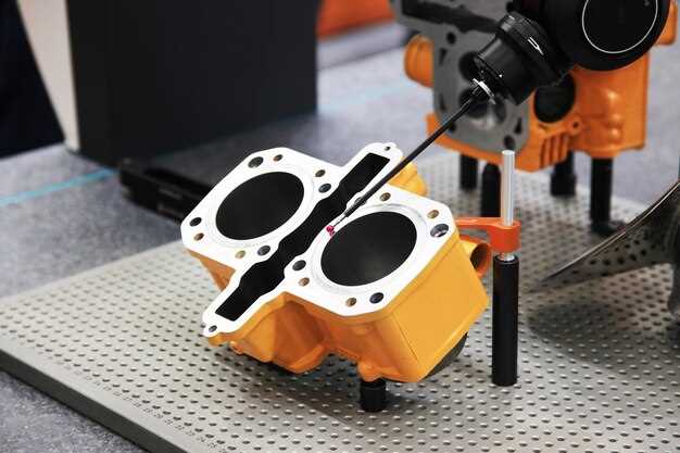
Validation and measurement rely on optical scanning or CMM data compared to the model, with metrics like surface roughness Ra and form deviation tracked against the plan. According to results, update the process window in the model and push new instructions to operators; this data-driven loop improves consistency and reduces waste.

Tools and automation play a big role: use low-dust bead blasting, vibratory finishing, and ultrasonic cleaning to handle challenging features. A dedicated shop-floor inventory of jigs maintains orientation and reduces handling errors. For some complex geometries, laser-textured finishing adds controlled roughness to aerodynamic surfaces; for exterior panels, bead blasting provides a matte finish and better paint adhesion, while delivering less drag on final parts.

Coatings and protective layers: apply aerospace-grade primer and top coats where needed; for sensitive assemblies, conformal coatings protect sensors and electronics. Ensure compatibility with subsequent assembly steps and paint plans. With a model-driven finish, options are evaluated against weight, drag, and durability; the production plan and company standards guide the final choice.

In-Service Inspection and Lifecycle Monitoring of AM Components

Implement a risk-based ISI protocol within 90 days of deployment and attach it to a formal lifecycle plan, with inspection intervals defined by material group, process route, and service exposure. This approach significantly lowers unexpected failures and meet safety margins across aerospace hardware.

Adopt a layered non-destructive testing (NDT) suite tailored to AM parts: phased-array ultrasonic testing for wall-thickness and crack-like flaws, radiography and computed tomography to reveal porosity and voids in metals and composites, and infrared thermography for surface and subsurface delaminations. For composites, prioritize delamination and fiber-failure checks, especially in parts with complex layups. These steps streamline data collection and support early issue detection.

Deliver results to a centralized inventory system to maintain traceability by serial, lot, material, and heat-treatment route. Link inspection outcomes to maintenance planning so that data from engines and other critical components informs renewal decisions; this inventory-centric approach reduces rework and improves efficiency across the supply chain, and presents them in a concise dashboard for planners.

Lifecycle monitoring leverages telemetry and periodic NDT results to drive condition-based maintenance: define replacement thresholds based on material properties, AM process, and service strain. Over time, this shift from reactive repairs to proactive planning delivers improvements in reliability and asset availability.

Address challenges by standardizing inspection criteria for composites and metals, training inspectors, and maintaining material traceability from feedstock to finished part. Innovation is strongest when you correlate inspection results with a history of issues seen in similar components; a whirlpool of data from multiple sources helps identify false positives and focus resources on high-risk areas. Use a conservative life-limit for classic designs like engines to ensure safety margins while freeing inventory for newer parts, which lowers risk and reduces lead times.