

 The Four Major Carbon Capture Technologies Explained – A Comprehensive Guide">

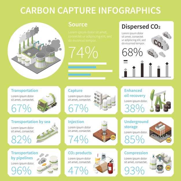
Start with post-combustion capture on existing facilities to cut CO2 emissions quickly and reliably. This move unlocks a practical path for companies to reduce emissions in the current fleet while new plants are being built and upgraded in the sector.
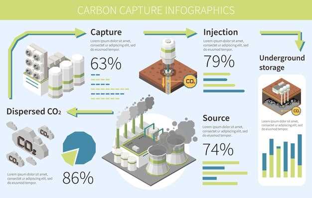
In this instance, post-combustion capture is widely deployed for CO2 separation from flue gases. It mainly uses solvent- or solid-based systems, and it separates CO2 from the gas stream before compression, enabling retrofit projects across multiple sectors. The price per ton varies by gas mix, plant size, and contract terms, with modular configurations helping to shorten deployment cycles and aid planning.
Pre-combustion capture works best in reforming-driven setups such as IGCC plants, where fuels are converted to synthesis gas and CO2 separates before combustion. The captured stream can be used for storage or downstream hydrogen production, supporting circular economy goals. In reforming lines, capital needs can be higher but energy penalties stay manageable when heat recovery is optimized, making a leading option for new-build facilities designed for long-term decarbonization.
Oxy-fuel combustion uses nearly pure oxygen to yield a CO2-rich exhaust that is easy to condition for storage. The modular retrofit path aids rapid deployment, but capital needs and energy penalties tend to be higher for smaller sites. Across the power and cement sectors, oxy-fuel remains a leading alternative when a site offers space for an air separation unit and dedicated furnace hardware.
Direct air capture pulls CO2 directly from ambient air, enabling removal of residual emissions and hard-to-abate sources. It carries a high price per ton (roughly $200–$600), depending on scale, energy supply, and policy incentives; modular DAC units allow siting far from major plants and can pair with waste-heat and renewable energy. Across multiple projects, DAC provides long-term removal capacity that aids climate targets and supports a circular approach to energy systems when integrated with storage and utilization options.
Across these four paths, a coordinated strategy helps lead the transition. Start with post-combustion on existing assets, then layer in pre-combustion or oxy-fuel where siting and heat integration permit, and reserve direct air capture for residual emissions and future-scale removal. This continuum continues to attract capital from a wide range of companies and financiers, with related data sharing and pilots speeding learning while reducing risk and expanding the sector’s capability to reforming energy and industrial systems for long-term decarbonization, aided by supportive policies and market mechanisms.
Post-combustion capture: retrofit options for existing plants and solvent choices
Recommendation: start retrofit with a monoethanolamine (MEA) baseline solvent loop and plan a later upgrade to an MDEA/piperazine (PZ) blend to gain higher capture at a lower energy penalty. This decision yields a solid result for cities aiming to cut emissions from fuels such as natural gas, coal, and waste-to-energy plants. Deploy a modular absorber close to the flue, connect to a regeneration loop, and compress the CO2 for pipeline transport. This fashion of staged retrofit helps demark the retrofit scope from new-build elements and keeps the plant operating within safe conditions. It also supports green goals and provides input to health authorities across european and global projects. Monitor solvent health, losses, and corrosion, and track nitrogen-related species in the flue gas to keep performance aligned as you scale up the plan.
Retrofit options within existing plants vary by flue gas composition, footprint, and energy tariffs. The most common route is to install an absorber tower and a stripper connected to the existing ductwork, with heat integration to recover energy from the hot rich solvent. A modular design enables later expansions; CO2 is compressed for pipeline or storage. In european markets, this approach lets projects advance with a clear path and measurable health and environmental benefits, while staying close to budget and schedule.
Retrofit pathway and equipment layout
Begin with a retrofit layout that uses a packed absorber and a lean/rich solvent loop, a staged reboiler, and a dedicated solvent reclaim line. Position the absorber downstream of the existing economizer to minimize pressure losses, and install a separate compact stripper to optimize energy use. Incorporate heat integration from the rich solvent to preheat the incoming streams, using waste heat where available. Maintain a conservative solvent circulation rate at start, then adjust based on monitored capture and energy results. This pathway keeps risks manageable, supports health and safety targets, and allows later upgrades without interrupting core operations.
Plan for optional nitrogen-selective steps if NOx co-removal or capture is pursued, and design for a modular capacity increase as the project signs new agreements or expands to additional fuels, including agricultural residues or other sources. The setup should be compatible with close integration to existing control systems and with future carbon management milestones in european and global contexts.
Solvent options and practical guidelines
| Solvent option | Typical capture (CO2) | Energy penalty (GJ/ton CO2) | Degradation/corrosion risk | Примечания |
|---|---|---|---|---|
| MEA (monoethanolamine) | 85–90% | 3.0–3.6 | High degradation and corrosion risk | Baseline, robust, widely used; simple integration with existing plants |
| MDEA (methyl diethanolamine) blends with PZ | 90–95% | 2.5–3.0 | Moderate degradation; good selectivity | Lower energy, well suited for large plants; supports nitrogen-selective performance |
| DEA (diethanolamine) | 75–85% | 2.8–3.4 | Moderate corrosion risk; slower reaction rates | Useful where MEA costs dominate; can be blended to balance performance |
| Amine blends with Piperazine (PZ) alone or with others | 85–92% | 2.7–3.1 | Corrosion and contamination management needed | Balanced performance; good for reducing energy penalty and improving kinetics |
| Ammonia-based capture | 60–80% | 2.0–3.0 | Lower solvent degradation risk; higher ammonia slip risk | Option for specific gas compositions or retrofit niches |
| Water/solvent blends (experimental or niche) | Variable | 2.5–3.5 | Lower stability in some cases | Used in pilot stages or for pilot-specific containment of degradation products |
Pre-combustion capture: gasification pathways, syngas cleanup, and heat integration
Start with an integrated gasification train that couples gasification, purification, and heat integration to maximize emission reductions and capture efficiency; this approach provides a source of syngas for multiple sectors and can deliver investment-ready performance in well-designed projects; youll see faster time-to-scale when you align milestones with data sharing and policy support across partners.
Gasification pathways
- Entrained-flow, oxygen-blown gasification delivers a consistent, hydrogen-rich syngas ideal for direct chemical synthesis and downstream upgrading; feedstocks include coal, petroleum coke, biomass, plastics, and even artificial waste streams; most plants operate with tight control over process time andor input variability, while working with robust preprocessing to hit the points of gas quality and precision.
- Fluidized-bed and moving-bed gasifiers provide robustness with a wider range of fuels, including some low-quality coal blends, biomass, and plastics; capital cost can be lower, but cleanup and tar reforming must be managed to maintain project economics and direct gas cleanup requirements.
Syngas cleanup and heat integration
- Cleanup steps remove H2S, COS, particulates, and sulfurous compounds; acid gas removal with Selexol or Rectisol, followed by water-gas shift to adjust the H2/CO ratio; purification yields a clean, CO2-rich stream suitable for direct capture, with gas purity targets typically >95% CO2 for most capture trains.
- Heat integration uses pinch analysis to recover high-temperature heat from the gasifier, shift reactors, and cleanup stages; feed that heat back to the reformer or steam cycle reduces fresh fuel input, lowers cost, and improves overall energy efficiency.
- Security and reliability: instrumented control and data logging maintain safe operation, close collaboration with suppliers, and secure energy supply across europe; direct collaboration with feedstock producers, chemical manufacturers, and logistics providers strengthens trust and reduces risk.
- Data and performance metrics: real-time composition, pressure, temperature, and energy balances enable precision control; this data helps optimize emission reductions and supports investor reporting – youll rely on this for continuous improvement and accountability.
- Feedstock flexibility and market connections: the gasification train can accept crops (crop residues), municipal waste, and even plastics from fashion and textiles; rail-enabled logistics moves feedstocks to plants close to markets, enabling cost-effective decarbonization across multiple sectors.
Finally, align policy incentives and investment to scale pre-combustion capture across europe; emphasize direct capture pathways, ensure security, and provide clear metrics on cost, reliability, and emission reductions to drive broad adoption and investor confidence.
Oxy-fuel capture: achieving a near-pure CO2 stream and combustion control considerations
Key design factors for stable oxy-fuel operation
Recommendation: Target a near-pure CO2 stream by using oxy-fuel combustion with high-purity oxygen, installing a robust CO2 purification and compression train, and planning storage at an appropriate site, allowing secure handling of CO2. This approach clearly yields a stream suitable for stored CO2 and makes it easier to meet reduction ambitions, with a defined term for capture performance. Ensure oxidant purity and flue gas recirculation are tuned to deliver >99% CO2 at the capture point, and include robust drying to remove moisture before storage.
First, regulate O2 injection and implement flue gas recirculation to balance heat release, preventing hotspots, particularly when the fuel is methane-rich. Use burner designs that promote intimate mixing of fuels and oxygen while avoiding local overheating. They should operate well under varying loads, with fast inline analyzers to track O2, CO2, and flame temperature, and apply real-time adjustments in the control system to stabilize the flame.
The oxy-fuel system works within a broader system that includes downstream CO2 processing, transport, and storage. Include data analytics and control loops that optimise performance; for example, using tools from google to monitor energy use, emissions, and CO2 purity. This approach supports planned projects and first movers seeking to reduce emissions while balancing the energy demand. It also helps across industries, including north American and united European contexts, to advance ambition toward greener operation and wider adoption.
Storage and environmental considerations: The captured CO2 is stored in geological reservoirs or other secure storage, with attention to safe volumes and pressure management. Ensure stored CO2 is kept away from sensitive ecosystems; this approach supports greener ecosystems by limiting emission and aligning with project term requirements. Planned pipelines and storage sites in united regions require coordinated planning, enabling widespread adoption and helping industries meet ambitious targets.
Balancing and end-user integration: Integrate oxy-fuel with energy storage and grid services to smooth operation during ramping, including batteries to cushion peak demand. The approach helps reduce overall energy intensity, optimise CO2 capture efficiency, and lower emission across the value chain, including for methane and other fuels. By linking projects with robust planning and continuous monitoring, they can respond to ambitions of widespread deployment across industries.
Direct air capture: siting criteria, energy requirements, and modular deployment challenges
Recommendation: build a capturemap to identify large-scale DAC opportunities with the lowest energy penalties and near-term storage options. Place first facilities in larger industrial clusters that have access to low-cost electricity, stable grids, and proven geological storage formations. Align siting with policy support and governments’ expectations to avoid misinterpreted analytics and to establish a clear, least-cost path for deployment.
Site selection and analytics
Key siting criteria include proximate, reliable energy supply (preferably low-carbon electricity or heat), access to geological reservoirs for CO2 storage, and land physically suitable for modular units and service corridors. Evaluate moisture levels and water constraints, since many DAC processes rely on moisture balance for sorbents or regeneration cycles. Use a categorisation scheme across sites: near-term hubs with robust infrastructure, regional storage capacity, and remote locations with transport considerations. Map distances for equipment delivery and CO2 transport; aim to minimize long truck routes and permitting complexity. Incorporate analytics to guard against misinterpreted signals and anchor decisions in transparent data layers on energy costs, storage capacity, land availability, and community acceptance. Where feasible, link siting to fertilizers or other CO2-utilisation options to broaden value streams.
Energy, moisture, and modular deployment
Energy requirements for DAC vary by technology; typical electricity demand ranges 0.5–1.5 MWh per tonne CO2, while heat needs can be 1.5–4 GJ per tonne, depending on whether heat is sourced on-site or from waste streams. Modular designs enable staged deployment, capital-light ramp-up, and easier siting; modules can be transported by truck and assembled on site, speeding deployment. However, deployment faces challenges in permitting, grid interconnection, and supply chain constraints for sorbents, compressors, and pumps. To balance costs and performance, plan larger-scale integration in phased steps that align with energy-supply commitments and storage capacity. Establish terms with utilities and equipment suppliers to keep contracts flexible and affordable. Consider tail-end risks in CO2 compression and transport, and ensure pipelines connect to suitable geological reservoirs. Maintain clear categorisation of capture levels and performance targets, and align with policy indicators and analytics dashboards to manage expectations and reporting.
Why categorise carbon capture techs: practical implications for policy, procurement, and project design
Recommendation: categorize carbon capture techs along three practical axes–deployment context, capture mechanism, and feedstock/source. This separation reduces policy ambiguity, clarifies procurement criteria, and guides project design. For instance, separate direct capture from biological approaches like trees and agricultural ecosystems, and distinguish offshore packaging and transport solutions from on-site operation. Use a shared datasets framework to track performance across accounts and bodies, then feed policy decisions with transparent metrics and related insights. This approach is especially promising for europe and japan, where policy pilots mainly target post-combustion capture and direct capture, with climate-resilient, clean energy integration.
Policy implications
Policy should use the categorisation to tailor funding, standards, and risk allocation. europe and japan have promising pilots across industrial post-combustion and direct capture, but policy clarity requires publishing a common taxonomy, with a direct mapping from category to supported incentives. Create three policy tracks: (1) climate-resilient, low-energy capture with hydro-powered electricity where feasible; (2) nature-based and BECCS options (trees, agricultural residues) integrated with agricultural policy and land-use planning; (3) offshore and shipping-enabled systems connected to CO2 transport infrastructure. Use datasets related to capture rates, energy penalties, storage integrity, and emissions accounting across bodies to inform upgrade cycles. Ensure reporting accounts separate by category to prevent cross-category misattribution.
Procurement and project design
Procurement should demand modular packaging for each category, enabling reuse across sites and easier upgrades as technology advances. Define a standard packaging interface, metric units for CO2 capture per year, energy penalty, and storage durability. For instance, a modular DAC unit and a solvent-based post-combustion stage can be procured as separate packages and then integrated on offshore platforms or on ships. Use a taxonomy to structure tenders by mainly captured streams (industrial, biogenic, or offshore) and by mobility requirements. In europe, a single procurement framework could bundle three packages–industrial, agricultural, and offshore–while japan pilots maintain separate accounts to track performance. Ensure project design prioritizes climate-resilient infrastructure, minimize transport distances for captured CO2, and plan for changing energy prices by including power and heat integration options.